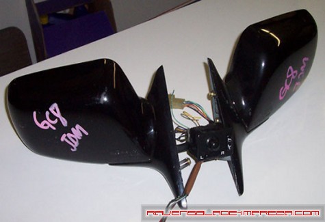
Mirrors As Purchased
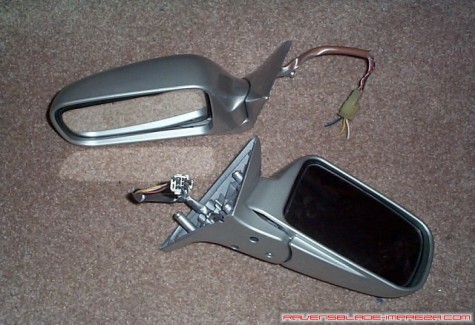
Mirrors After A Fresh Coat Of Silverthorn Metallic Paint
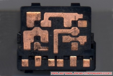
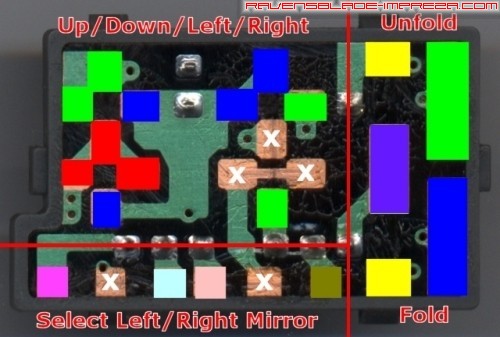
PCB Of Stock 2000 RS Mirror Switch

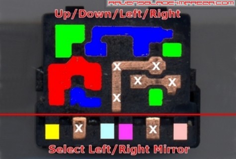
PCB Of JDM v6 STi Mirror Switch
Above, you can see the printed circuit board (PCB) for the stock switches. These are located underneath the portion of the switches that you normally see when using the switch. As you can see, the circuit boards are different, but the layout for up/down/left/right control and the left/right mirror selector is logically the same.
Stock 2000 Impreza RS Mirror Switch
JDM STi v6 Mirror Switch

Pinout shows stock connector from the wire side

Pinout shows STi connector from the wire side
I took out a multimeter and went nuts, testing each spot on the PCB and looking for a voltage reading associated with a pin on the connector. The images above show where each spot on the PCB joined with what pin on the connector. Please note that the PCB views are from the front, though the color diagrams are taken from the wire side of the connector (basically, as you would view the pins on the switch if you looked down into the connector at them). As you can see, apart from the fold/unfold portion of the JDM switch, the two switches are identical, though the colors I ended up assigning them are different.
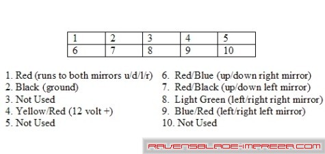
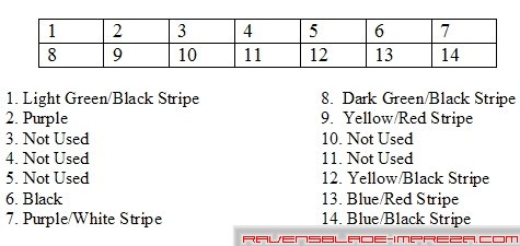
Here, you see a diagram of the pinouts (again, from the wire side) plus their corresponding colored wires. For the stock switch on the top, I have included the function of each wire, as it was simple to discern from the service manuals. I didn't have that information at the time of making these pinout charts (I used them to solicit help from the Subaru community on how to wire these up) so the JDM switch does not have the function associated with the wire color. Keep in mind, these wire colors will likely be different on non-2000 Impreza RS models, as will the wire colors on non v6 STi JDM switches.
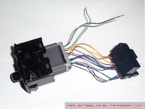
I am a firm believer in doing things elegantly whenever possible, and to that end, I did not want to cut up my stock wiring harness to get this project going. Besides being messy and the connections being uncertain, if the JDM switch should ever blow out or should I ever need to go back to stock, it will be entirely more difficult than need be. I sought out another stock USDM mirror control switch (part number 83071FA030) to use as a sacrificial connector for the JDM switch. This way, I use a click connector to attach the JDM switch to the stock body harness (granted, this leaves two wires left over I have to run by hand, but it is almost perfect) and still retain my stock switch as a backup. A photo of what I am getting at is pasted in below:
How I got to that point is fairly simple. I took the wires from the JDM switch, and soldered them to corresponding spots on the USDM switch PCB. A photo of the finished product and a diagram of what went where is below. You will need to refer to the JDM wiring pinout diagram I showed earlier to understand the wiring diagram below- the numbers in white refer to the wire number in those diagrams:

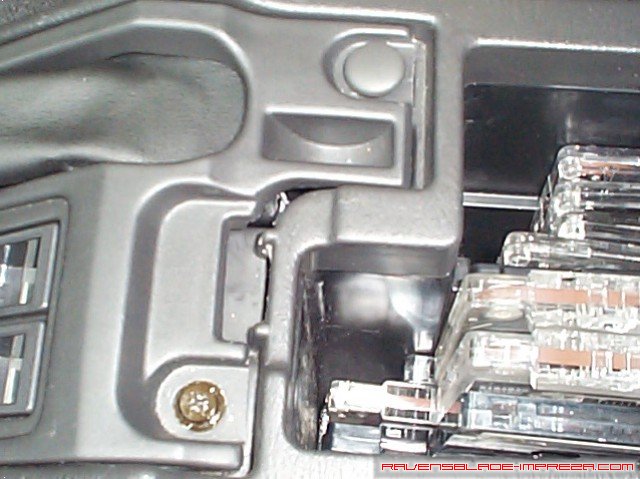
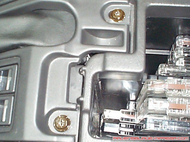
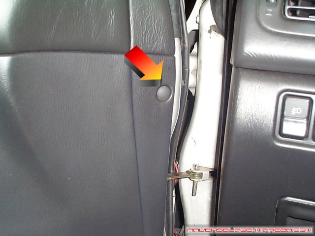
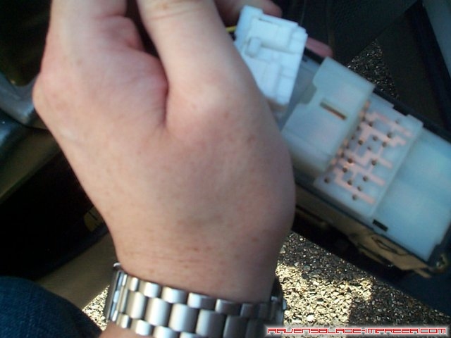
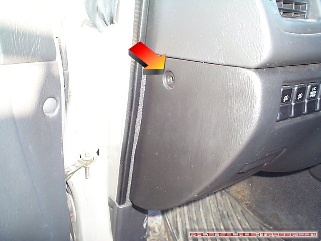
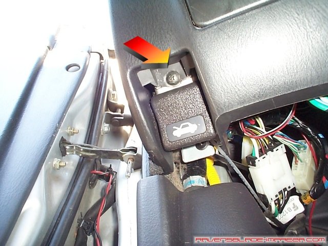
You will need to remove your center console to put this switch in, so make sure the parking brake is engaged, and then open the center console cover, and locate the two screw caps. One has been pulled off above to illustrate. They just pop off if you gently pry up under them with a flathead screwdriver. There are two phillips screws that need to be removed under those caps, as seen below.
After removing those, pull up and forward on the center console, lifting it up and over the brake lever. Disconnect the harness for the mirror controls, push the old switch out by pressing on the clips on the back, and insert the new switch.
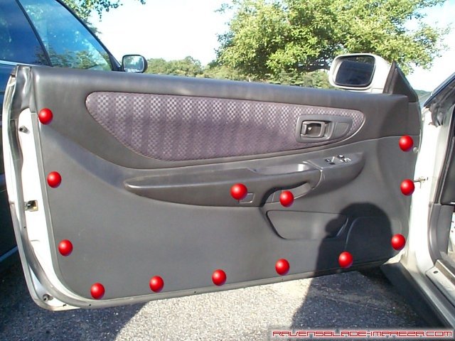
Let's get down to business. This photo shows the locations of all the fasteners holding the door panel on. Mostly push clips, but two screws are located in the armrest section as well.

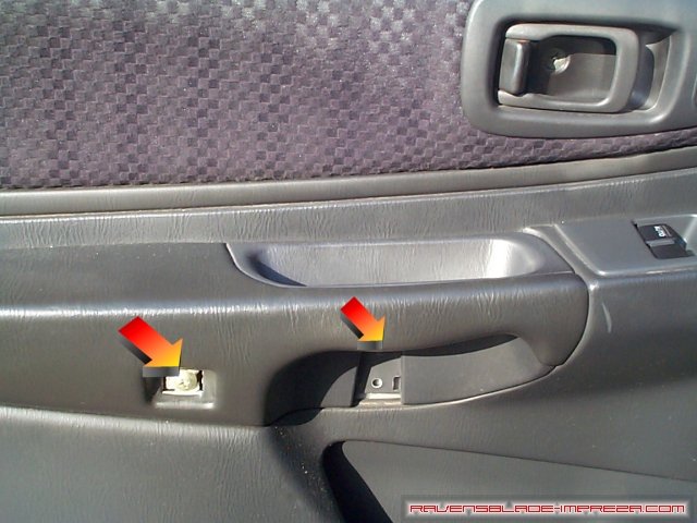
There are covers over the screws, this one pictured and one just to the side of it (about 3" away). Slide a small tool wide enough to not mar the door panel in behind them and pull them up to expose the screws.
This is a photo of the two covers removed. The gold screw is easy to see, but it's a bit harder to see the black screw (it's tucked up at the top of the odd-shaped hole on the right in this photo).
After removing the two screws, remove the trim around the door pull. You do not need to remove the screw located in the door pull cup. Just stick you fingers in behind the trim and pull gently- it will pop off.
Remove the corner cover in a similar fashion to the door screw covers. Note the three brass colored screws behind this cover that you will be removing later.
Lastly, remove the small push rivet in the front edge of the door. Pry up on it gently- you may wish to protect the door panel with a rag or some thick cardboard, as this fastener is recessed.
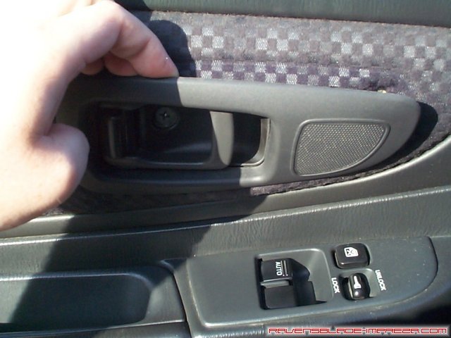
This will be easier to do with your window down, so I advise you lower it all the way now. Next, reach down to the bottom of the door panel and feel for the open area towards the back edge of the door. There will be plenty of room to stick your fingers in and pull the door panel towards you gently. Follow all around the edge pulling out the push connectors, and then pull the whole panel (grab the door pull) straight up and off the door- it will be completely free after only an inch or two. Be gentle, as the window and door lock controls are still connected. Some people question why I do not remove the switch section before the door panel, and the answer is because they break too easily. I would rather be careful to not pull the door cover too hard than break the rather fragile clips that hold the switch section into the door, not to mention the door panels are easy to scratch and this prevents damage when removing the switch section. To that end, once you have the door panel off of the door, pull the top towards you gently, and you will see the whole switch. Push it gently up and out of the door panel from below.
With the switch section out of the door panel, it is easy to disconnect it from the wiring. Set the switch section aside in a safe place, and do the same for the door panel.
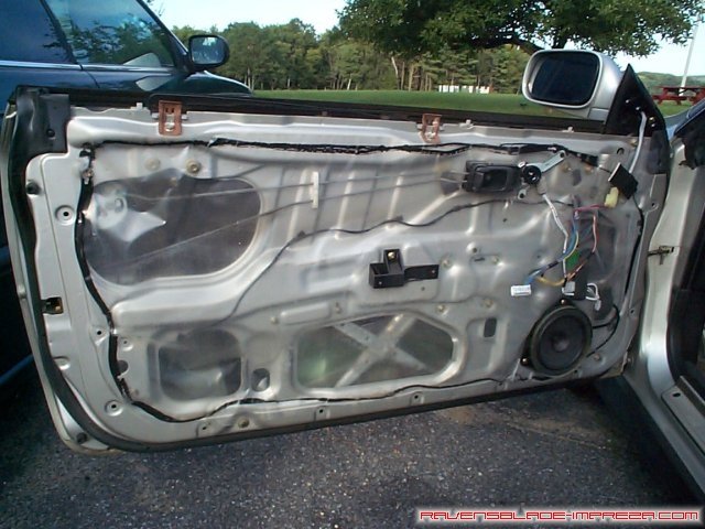
There we go- a bare door. The section we are concerned with is there in the upper right corner of the photo.
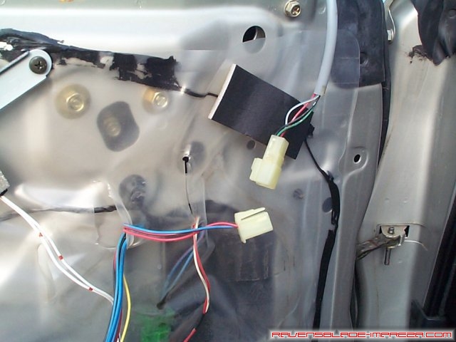
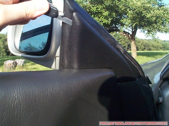
Follow the wire from the mirror down to the connector and disconnect it.
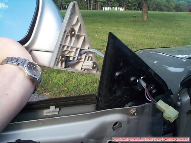
Remove the three brass colored screws mentioned earlier one at a time, and pull the mirror up and away from the body of the car, passing the wiring harness through the hole. Reverse the process and attach your new folding mirror.

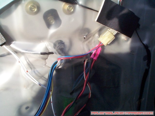
Hopefully, you were fortunate enough to get both sides of the connector, like I was. There are two extra wires per connector on the folding harness that are not present on the stock harness, and having the other side of the connector means you have the pins as well. I simply added several feet of wire (one piece red, one piece black for ease of wiring later) using good waterproof crimps, and removed the pins from the connector with a small pick. I then placed them into the stock connector- thank you Subaru for using similar connectors across all models! A diagram of what I did is below:
 
As you can see, the USA connector (on the left) and the JDM connector (on the right) are identical for most of the controls (up, down, left, right) and the JDM harness just adds two more pins (fold and unfold). I pulled them out of the JDM harness and then moved them to the USA harness in the car, so that the USA harness looks just like the JDM one. Do this the same for both mirrors. If you did not get the other side of the JDM harness, you are going to have to cut/splice into the mirror side to make your connections. Just make sure they are solid connections- use waterproof connectors or solder them.
After adding the two pins, I attached the folding mirror harness to the modified USA harness.
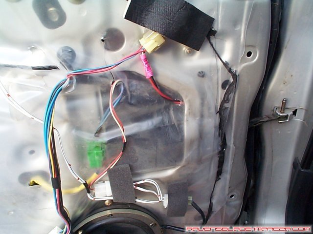
Here is where elegance failed me. I tried just about everything I could think of to run the two new wires along the same conduit through the door into the body of the car. It is just too tight to do without dismantling the door. I was not up for that kind of challenge, nor do I think it is necessary. I pushed a small hole through the plastic seal and fed the wires through it.
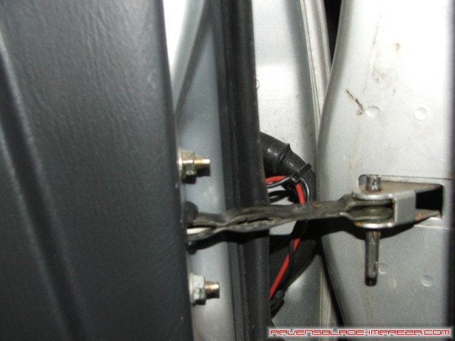
After pushing the wires forward, push them out along the harness going through the weatherseal in the door, and use some zip ties to fasten it to the cable. This will help prevent pinching the wires.
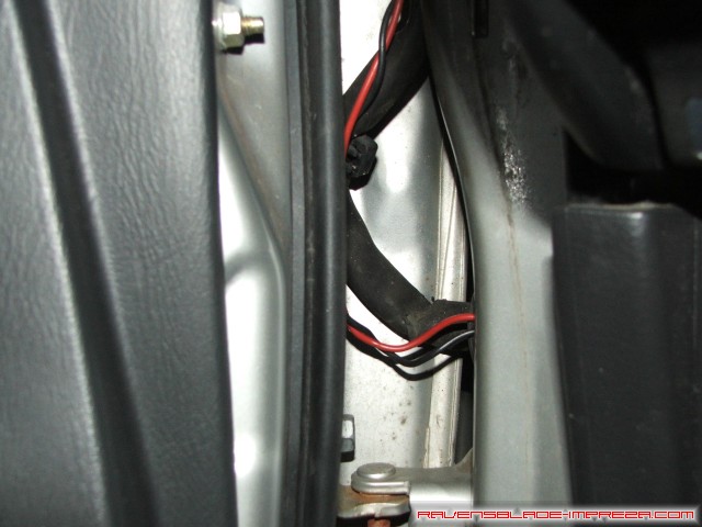
Now, pull out the weatherseal on the body side a little, and push the wires through to the interior of the car.
Make sure you replace the seal as best you can.
Next, pull the plastic rivet out on the side of the dash by giving the center 1/4 turn with a screwdriver, and pulling out.
Next, remove the screw by the hood release
Now remove the screw on the other end of this panel, by the center console.
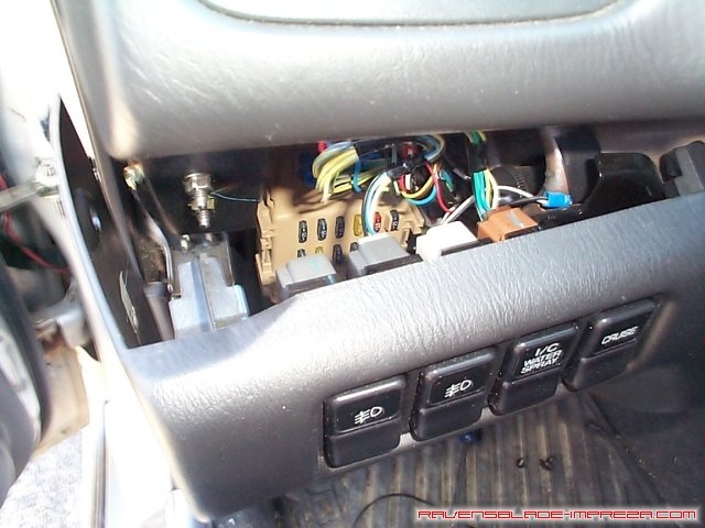
Gently pull outward by the fog switches, and reach behind and disconnect them by pushing on the tab and pulling away from you. Here, you see two connected and two disconnected and you can see where they will come apart.
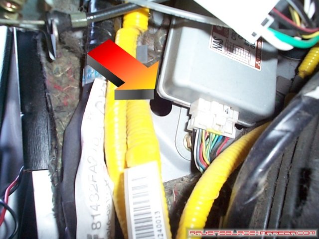
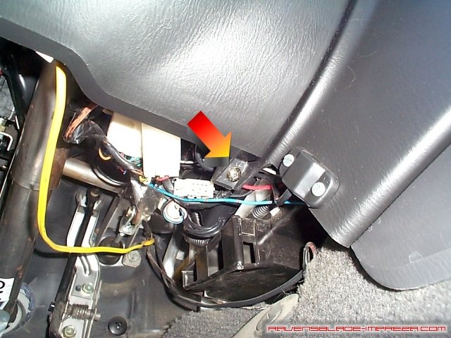
Next, look just above the footrest, and you should see this hole. With a pair of needle nosed pliers, you should be able to pull the wires through this hole. Run the wires along towards the center console, being very careful to thoroughly tape or zip tie them out of the way- you do not want anything getting in the way of the pedals! Now, run the wires towards the mirror switch- you can very easily slip the wires between the center console and the carpet all the way back. Pull the loose ends of the wire up inside of the mirror switch area.
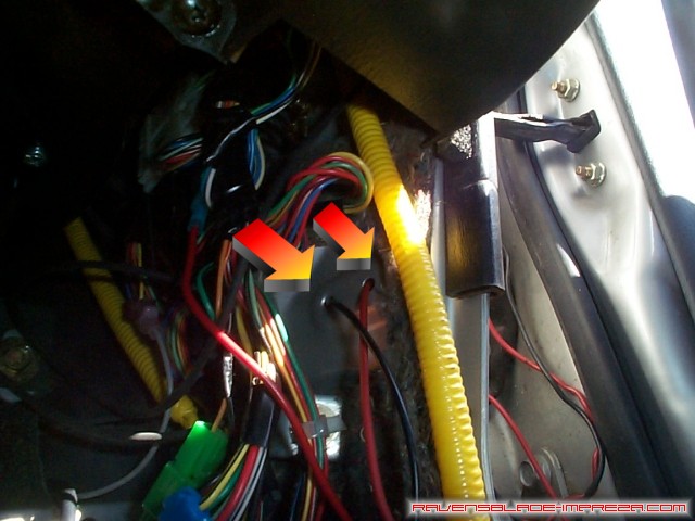
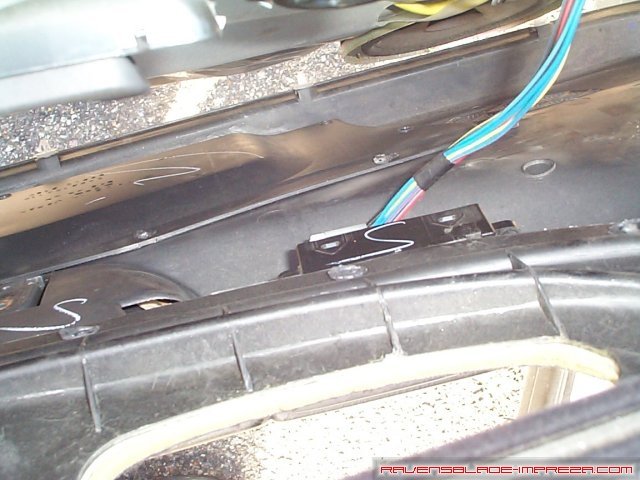
Back to the other side of the car now. There is no easy hole like on the driver side to put the wires through, so I used two pieces of wire instead of one on this side. One piece runs in from the door, and then I ran the wires out these two small holes. Push the wires in and pull out the seal on the body side of the harness. You should be able to push them right out the hole.
Here, I have joined the inside wires and the ones from the door with waterproof splices; I have taped them up for extra measure.
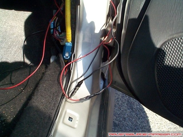
Pull the wires through the weather seal, and neaten up the wires with zip ties and replace the seal just like was done to the driver side.

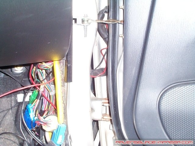
Just like before, run your wires to the center console, and secure them out of the way. Pull the wires along and under the console, and pull them up in the mirror switch area as well.
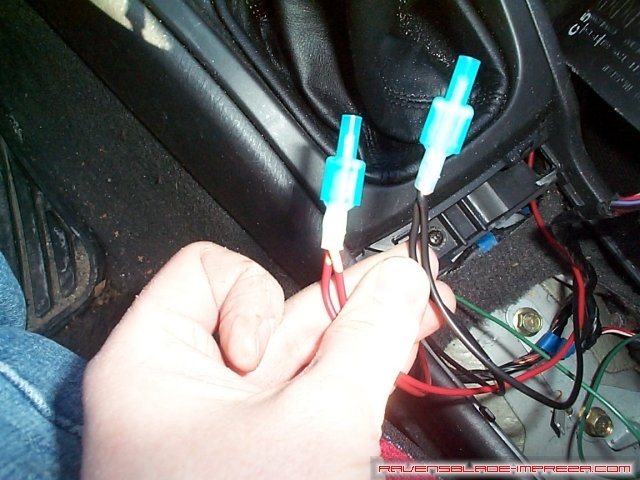
Now, take your two black wires and your two red wires, and put them into a single connector like this. I used quick disconnects for future removability, but you could use butt connectors if you wish.
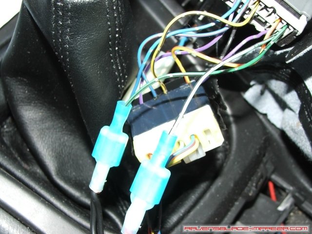
The final connections! Connect the light green wire with the black stripe to the red wires, and the dark green wire with the black stripe to the black wires. Turn your ignition on and test the mirrors at this point- they should work flawlessly.
Want a quick video of the automagic folding mirror action? (569KB)
|
|
